How UK Boundaries Are Measured From the 1935 Retriangulation to Modern RTK GNSS — the coordinate system behind every property title plan in England and Wales
Every red line on an HMLR title plan traces back to a theodolite on a hilltop in 1937. This guide explains how Great Britain was measured, how the Ordnance Survey National Grid was built, why GPS coordinates need transforming before they match a title plan — and which satellite technologies give you centimetre accuracy on the ground today.
How Britain Was Measured — An Introduction
Before the first GPS satellite reached orbit, before digital computers, every property boundary in England and Wales was anchored to a network of stone pillars placed on hilltops by hand. The accuracy of your title plan today traces back to a surveyor standing on a Welsh mountain in 1937, pressing his eye to a theodolite, measuring an angle to a hilltop in Shropshire thirty miles away.
This guide traces the complete story of how Great Britain was measured — from William Roy’s first accurate military survey of the 1780s, through the Retriangulation of Great Britain (1935–1962) and the creation of OSGB36, through the arrival of GPS satellites and the OSTN15 transformation that bridges the two systems, to the multi-constellation GNSS receivers and RTK correction networks available today.
It answers the question that confuses almost every GPS user in the UK: why does a coordinate from a GPS receiver not land precisely on an Ordnance Survey map without a correction? The answer involves two different mathematical models of the Earth, 6,500 concrete pillars, and a transformation grid published in 2015.
- How the Retriangulation built the geodetic framework for all UK mapping
- What OSGB36 is and why it is still the datum used for land registration
- How GPS (WGS84) differs from OS coordinates — and by how much
- What OSTN15 does and why it achieves ~10 cm accuracy
- How RTK corrections reach 1–3 cm and how NTRIP delivers them
- Which satellite constellations are visible from the UK and what each adds
- What equipment is available and what it costs
If you are trying to locate your physical boundary markers on the ground — buried pegs, iron pins, or overgrown corners — BoundaryFinder lets you connect a Bluetooth GNSS receiver or RTK rover directly to the preview page to achieve 1–3 cm positioning against your registered title boundary.
Find Boundary Markers Guide ›The Triangulation Era — Trig Stations & Theodolites (1935–1962)

A concrete trig pillar — one of approximately 6,500 built across Great Britain between 1935 and 1962.
Before satellites, before computers, Ordnance Survey mapped the entire country by looking at it — literally. Between 1935 and 1962, surveyors constructed approximately 6,500 concrete pillars on hilltops, mountain summits, and prominent landmarks across Great Britain. These are trig stations (triangulation stations), and almost every one is still standing today.
The project was formally known as the Retriangulation of Great Britain. Its purpose was to create a new, rigorous geodetic framework for the country — a mathematical skeleton of precisely known points from which all other mapping could be derived.
How Triangulation Works
Triangulation is a method of determining the position of an unknown point by measuring angles from two known points. If you know the exact position of A and B, and you can measure the angle at which C appears from both A and B, you can calculate the exact position of C by trigonometry. Repeat this across an entire country, each new point becoming the basis for the next, and you build a national coordinate network of extraordinary precision.
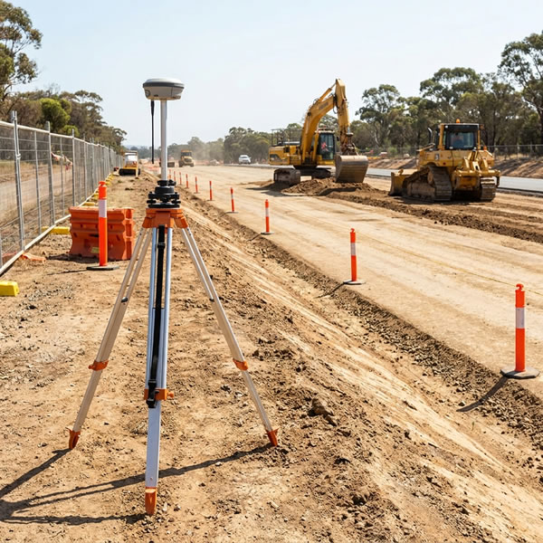
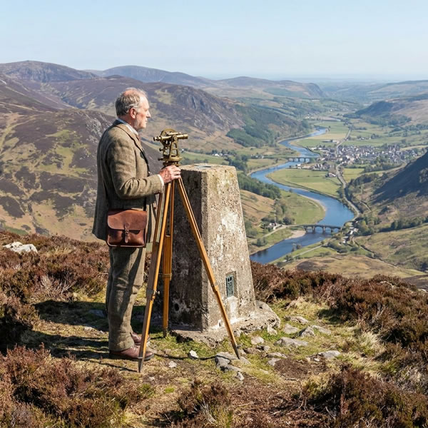
The key instrument was the theodolite — an optical instrument mounted on a precision tripod that measures horizontal and vertical angles to a target with great accuracy. A surveyor would set up the theodolite on a trig pillar, sight it towards the bronze spider fitting on a distant pillar, and record the angle. The concrete pillars were designed to hold the theodolite at a standard height with the optical axis centred precisely over the survey mark.

A precision theodolite on a tripod — the principal instrument of the retriangulation. It measures horizontal and vertical angles with arc-second precision.
How Many Trig Stations Are There?
Ordnance Survey built 6,190 trig pillars in Great Britain as part of the retriangulation, plus several hundred supplementary and secondary stations. The network was completed in 1962 and used as the primary control framework for all national mapping until GPS made it obsolete in the 1980s and 1990s.
Today the trig network is fully decommissioned for professional surveying. OS now uses a network of continuous GNSS reference stations (OS Net) and LiDAR aerial surveys to maintain national mapping. The concrete pillars themselves, however, are largely intact and have become popular hiking destinations — a pastime known as “trig bagging” with an active community of walkers who visit and log every one.
Ordnance Survey publishes the full database of trig pillar positions, including coordinates, condition reports, and photos submitted by walkers. You can browse and download the complete dataset at trigpointinguk.com and at the OS Data Hub. Many walking and GPS apps include trig stations as points of interest.
Before OSGB36 — Roy’s Survey and the Airy Ellipsoid
The 1935 retriangulation was not Britain’s first attempt at systematic national mapping — it was a correction of an older, less accurate one. To understand why OSGB36 exists, you need to understand what it replaced.
General Roy’s Military Survey (1747–1755)
In the aftermath of the Jacobite rising of 1745, the British government commissioned a military survey of Scotland to aid in suppressing further uprisings. Conducted under General William Roy, the survey covered most of Scotland between 1747 and 1755 and produced detailed manuscript maps showing terrain, roads, settlements, and rivers. It was the most systematic survey of any part of Britain up to that point.
Roy went on to measure a precise baseline on Hounslow Heath in 1784 — a distance of approximately 5 miles measured with great care using glass rods and steel chains. This baseline became the starting point for triangulation that extended across the channel to France, laying the groundwork for the first formal Ordnance Survey of Britain.
The Airy 1830 Ellipsoid
The Earth is not a sphere — it bulges slightly at the equator and is flattened at the poles. To perform accurate surveying calculations, you need a mathematical model of the Earth’s shape called an ellipsoid. In 1830, the Astronomer Royal Sir George Airy computed the best-fit ellipsoid for Great Britain by analysing triangulation data. This became known as the Airy 1830 ellipsoid.
The Airy ellipsoid fits Great Britain extremely well — but it does not fit the rest of the world. It was designed to minimise errors across the UK, which means it diverges from the true shape of the Earth as you move further away. This is not a problem for UK mapping, but it does mean that Airy-based coordinates and global satellite coordinates are not directly comparable — a fact that would become significant 150 years later when GPS arrived.
The National Grid & OSGB36
The retriangulation of 1935–1962 produced a new national coordinate system: OSGB36 (Ordnance Survey Great Britain 1936). This became the geodetic datum for all UK mapping — the reference framework from which all coordinates, grid references, and title plan boundaries are derived.
How the National Grid Works
The British National Grid (BNG) is a Cartesian coordinate system projected onto the Airy ellipsoid. It uses a modified Transverse Mercator projection, meaning the curved surface of the Earth is mathematically “unwrapped” onto a flat grid. The grid is divided into 100 km × 100 km squares, each labelled with two letters (e.g. TQ for central London, NT for Edinburgh). Within each square, a position is given as an Easting (distance east) and Northing (distance north) in metres.
The origin of the grid is a false origin — a point 400 km west and 100 km north of a “true” origin in the Atlantic Ocean south-west of the Isles of Scilly. This ensures all coordinates within Great Britain are positive numbers, avoiding negative values in the south-west.
The National Grid reference system is used in Ordnance Survey maps, HM Land Registry title plans, INSPIRE boundary polygons, OS MasterMap, emergency services, and the military. Despite the arrival of GPS and lat/lng coordinates, the National Grid remains the primary coordinate system for UK land use, planning, and property law.
BoundaryFinder provides BNG easting/northing coordinates for every boundary corner alongside WGS84 lat/lng, because both systems are used by different professional tools.
Benchmarks, the “V” Symbol & Ordnance Datum Newlyn

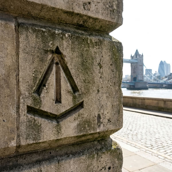
An Ordnance Survey benchmark cut into a stone wall — the horizontal bar with V notch above it indicates a precisely known elevation above Ordnance Datum Newlyn.
If you have ever noticed a curious symbol cut into an old stone wall, bridge, church, or building — a broad arrow pointing upward with a horizontal bar and a V-shaped notch above it — you have found an Ordnance Survey benchmark. There are approximately 500,000 of these marks across Great Britain.
A benchmark is a point of precisely known elevation. A licensed surveyor measured its height above a reference level — the Ordnance Datum Newlyn (ODN) — and carved the symbol to mark it permanently. Any subsequent surveyor who needed to know an elevation could start from a nearby benchmark rather than re-measuring from scratch.
Ordnance Datum Newlyn — Mean Sea Level
Ordnance Datum Newlyn is the official zero-elevation reference for Great Britain. It is based on the mean sea level measured at Newlyn, Cornwall, averaged over the period 1915–1921. Why Newlyn? The port was chosen for its sheltered tidal gauge position and its distance from the North Sea, which experiences more complex tidal patterns. The six-year averaging period was chosen to cancel out seasonal and storm variations.
Every benchmark in Great Britain, every contour line on every OS map, and every elevation quoted in UK construction and engineering is ultimately referenced to this single point on the Cornish coast.
Cadastral Lines
In land registration and surveying, cadastral refers to the detailed map of property boundaries — the lines that define ownership. In the UK, the cadastral record is held by HM Land Registry as the INSPIRE Index Polygons dataset. These are the same boundary outlines that BoundaryFinder uses. Every line in that dataset traces back, through the chain of mapping described on this page, to the trig stations and benchmarks of the mid-twentieth century.
Like trig stations, OS benchmarks are now decommissioned for active surveying — modern levelling uses GPS and LiDAR. The physical marks remain, however, and are well documented. The OS Benchmark dataset, listing the position and elevation of all 500,000 marks, is available for download through the OS Data Hub. They are a remarkable piece of industrial heritage, found on almost every Victorian-era structure in the country.
The Satellite Era — GPS, WGS84 and the Coordinate Problem

The first GPS satellite (Block I, NAVSTAR-1) was launched by the United States Air Force in February 1978.
On 22 February 1978, the United States Air Force launched the first GPS satellite — NAVSTAR-1. The system, developed under the US Department of Defense, aimed to give military assets a precise global position at any time, in any weather. By 1993 the full constellation of 24 satellites was operational, and civilian access had been opened to the world.
GPS works by timing. Each satellite broadcasts a signal containing its precise orbital position and the exact time of transmission. A GPS receiver picks up signals from at least four satellites simultaneously, computes the time delay for each signal to arrive, and from those delays calculates its distance from each satellite. With four distances known and the satellite positions known, the receiver can solve for its three-dimensional position.
WGS84 — The Global Datum
GPS uses a global coordinate system called WGS84 (World Geodetic System 1984). WGS84 uses a different ellipsoid from the Airy 1830 used by OSGB36 — one designed to fit the entire Earth, not just Great Britain. The WGS84 ellipsoid has a larger equatorial radius and a different flattening ratio. As a result, WGS84 coordinates and OSGB36 coordinates for the same point on the ground are different numbers — offset by up to 7 metres in the UK.
ETRS89 (European Terrestrial Reference System 1989) is the European equivalent of WGS84. It is essentially identical to WGS84 for practical purposes, but is fixed to the Eurasian tectonic plate. In the UK, ETRS89 and WGS84 differ by only a few centimetres and the terms are often used interchangeably in a surveying context.
When your phone gives you a lat/lng coordinate, it is in WGS84. When a UK property boundary is described in a title plan, it is plotted in OSGB36. These two coordinate systems, using different mathematical models of the Earth, can disagree by up to 7 metres for the same point in the UK.
This means you cannot simply take a GPS lat/lng and plot it on an OS map, or take an OS grid reference and assume a GPS will find it at the stated location. A mathematical transformation is required. That transformation is called OSTN15.
Bridging the Gap — OSTN15
OSTN15 (Ordnance Survey National Transformation 2015) is a high-accuracy grid-based datum transformation that converts between ETRS89/WGS84 coordinates and OSGB36 National Grid coordinates. It is the official transformation used by Ordnance Survey, HM Land Registry, and any professional surveying application that works with UK data.
How OSTN15 Works
Rather than a single mathematical formula (which cannot perfectly account for the distortions accumulated over decades of ground-based triangulation), OSTN15 uses a grid of shift values covering the whole of Great Britain. At each grid node, a precise horizontal shift (eastings and northings separately) has been measured by comparing ETRS89 GPS positions against established OSGB36 control points. When converting a GPS position, the software reads the surrounding shift values, interpolates between them, and applies the result.
OSTN15 achieves an accuracy of approximately 10 cm relative to the OSGB36 datum across the UK. It replaced OSTN02, which had accuracy of approximately 15 cm, and the older simple-formula methods that could introduce errors of several metres.
BoundaryFinder applies the OSTN15 transformation to all INSPIRE polygon coordinates. The GPS lat/lng coordinates shown for each boundary corner are the result of a full OSTN15 conversion — not a simple formula approximation. This means our WGS84 coordinates and our BNG easting/northing values are consistent with each other and with the HMLR source data to the maximum precision the transformation allows.
Global Satellite Constellations
GPS was not the last word. Today, four major global navigation satellite systems (GNSS) are operational, and a modern GNSS receiver uses signals from all of them simultaneously. More satellites in view means better position geometry, faster acquisition, and improved accuracy — particularly in urban canyons or under tree cover where some satellites are obscured.
31 active satellites in 6 orbital planes at 20,200 km altitude. Fully operational since 1993. The original global civilian navigation system. Accuracy: ~3–5 m standalone (civilian L1). Modern L5 signal: sub-metre with dual-frequency receivers.
24 active satellites in 3 orbital planes at 19,100 km altitude. Operational since 1995. Russia’s equivalent of GPS. Uses slightly different frequency-division multiple access (FDMA) signal design from GPS. Adds significant additional coverage at high latitudes, benefiting UK users.
30 active satellites (24 operational + 6 spare) in 3 orbital planes at 23,222 km altitude. Full operational capability declared 2024. Civilian-owned and civilian-operated. High-accuracy open service with better signal than GPS L1, particularly for RTK. All modern smartphones and GNSS receivers receive Galileo.
35 active satellites (GEO + IGSO + MEO) at varying altitudes. Global service fully operational since 2020. Primarily serves Asia-Pacific but provides useful additional satellites over the UK. Higher signal count improves fix reliability, especially under tree cover.
A modern multi-constellation GNSS receiver — including most smartphones from 2017 onwards — can track all four systems simultaneously. In an open sky in the UK, a receiver will typically see 20–35 satellites at once. The position is calculated from all visible signals combined, weighted by signal quality. The result is significantly more reliable and faster to acquire than GPS alone.
Modern Precision — RTK, NTRIP and Cadastral Accuracy

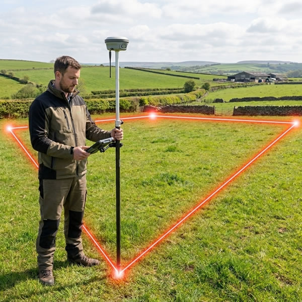
An RTK rover receiving NTRIP corrections over 4G. The correction stream from a nearby OS Net reference station reduces positioning error from metres to centimetres.
Standard GNSS achieves 2–5 m accuracy because satellite signals are subtly distorted as they pass through the ionosphere and troposphere — charged layers of the atmosphere. RTK (Real-Time Kinematic) positioning solves this by comparing what a receiver sees to what a fixed reference station at a known position sees at the same moment. The atmospheric distortions are nearly identical for both, so they can be subtracted out. What remains is an extremely precise position — typically 1–3 cm.
How NTRIP Delivers Corrections
For RTK to work, the rover receiver needs a live stream of correction data from a reference station. In modern practice, this is delivered over the internet using a protocol called NTRIP (Networked Transport of RTCM via Internet Protocol). A network of fixed reference stations (a caster) broadcasts correction data continuously. The rover connects to the caster over 4G, receives the correction stream, and applies it in real time.
Most UK casters use Virtual Reference Stations (VRS). Rather than connecting to a single physical station (which might be 50 km away), the caster generates a synthetic correction stream as if there were a reference station right next to you. This is computed from the surrounding real stations and dramatically improves accuracy over long baselines.
| Positioning mode | Typical accuracy | Setup required |
|---|---|---|
| Phone GPS | 3–15 m | None |
| Bluetooth GNSS dongle (standalone) | 1.5–3 m | Pair once in phone Settings |
| GNSS + DGPS (free correction) | 0.5–1.5 m | Automatic for most receivers |
| GNSS + RTK Float | 0.1–0.5 m | NTRIP subscription + credentials |
| GNSS + RTK Fixed | 0.01–0.05 m | NTRIP + 30–60 s initialisation |
UK NTRIP Casters
NTRIP casters are subscription services. The customer brings their own account — BoundaryFinder provides the connection interface. The major UK options are:
- OS Net (Ordnance Survey) — 110 reference stations across Great Britain, spacing ~60–70 km. ~£500/year. The standard choice for professional UK surveying.
- Leica SmartNet — Commercial network with ~100 stations. ~£600–800/year. Popular in construction and engineering.
- Trimble TopNET Live — Similar commercial network. ~£600/year. Widely used by registered surveyors.
- EUREF-IP — Free European network. Sparse UK coverage, suitable for development and testing only.
What You Can Buy

An Emlid Reach RS2 used as a base station. Set over a known point, it broadcasts corrections to one or more rovers working in the field.
The GNSS receiver market spans a very wide range — from a £35 USB dongle to a £8,000 survey-grade total station. The right choice depends entirely on the accuracy you need and how often you will use it.
A compact receiver based on a u-blox M8 or M10 chip, connecting to a phone or tablet via Bluetooth. Typical accuracy 1.5–3 m. Works immediately with BoundaryFinder’s Connect GNSS Receiver feature. No subscription, no setup beyond a one-time Bluetooth pair.
- Examples: Garmin GLO 2, Bad Elf Pro, Columbus V-990
- Suitable for: boundary inspection, general land navigation
A multi-constellation receiver with a larger survey-grade antenna. Supports dual-frequency signals for improved accuracy (sub-metre) and can receive RTK corrections when paired with an NTRIP subscription. Connects via Bluetooth or USB.
- Examples: Trimble R1, Leica Zeno 20, u-blox F9P (developer)
- Suitable for: property inspection, estate agent site visits, planning
A self-contained RTK receiver with built-in 4G and WiFi for direct NTRIP connection. 1–3 cm accuracy on RTK Fixed. Some units (e.g. Emlid RS2/RS3) can operate as both rover and base station, creating a local correction network without an external subscription.
- Examples: Emlid Reach RS2+, RS3, Trimble R10, Leica GS18
- Suitable for: surveyors, boundary disputes, planning applications
BoundaryFinder works with any GNSS receiver that exposes a serial (Web Serial) port to the browser — which covers virtually all Bluetooth receivers when connected via your phone’s Bluetooth-to-serial bridge. There is no app to download, no account required for Bluetooth connection, and no proprietary format. Your receiver, your data.
RTK corrections via OS Net, SmartNet, and TopNET are supported through the built-in NTRIP proxy. Enter your caster credentials once and BoundaryFinder handles the connection, the RTCM stream, and the GGA feedback loop required by VRS casters — all in the browser.
Trig Station — Concrete Triangulation Pillar
Theodolite on Tripod

Ordnance Survey Benchmark — V Symbol
Early GPS Satellite — NAVSTAR Block I (1978)

RTK Rover in the Field
RTK Base Station